Comprehensive Engineering Guide: Demystifying the 12F-N20 Micro Spur Gear Motor for Precision Motion Control
In an era defined by miniaturization, smart automation, and wearable technology, mechanical design engineers face a continuous challenge: how to deliver maximum torque and precise angular motion within increasingly tight spatial constraints. Whether you are building next-generation medical infusion pumps, autonomous micro-robotics, or intelligent locking mechanisms, selecting the right micro-actuator is paramount to product performance, power efficiency, and long-term reliability.
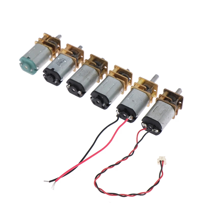
Among the wide variety of miniature motor assemblies available on the market today, the 12F-N20 micro spur gear motor stands out as an industry-standard workhorse. Combining a compact N20 core DC motor with a flat 12mm spur gearhead, this micro-gear motor delivers an optimal balance of cost-effectiveness, energy efficiency, and mechanical reliability.
This engineering guide provides an in-depth exploration of spur gearing principles, analyzes the technical specs of the 12F-N20 Micro Spur Gear Motor, compares spur versus planetary micro-gearheads, and provides practical integration guidelines for hardware developers.
1. Fundamentals of Micro Spur Gear Motors
To understand why the 12F-N20 is so widely adopted, we must first look at the mechanical architecture of spur gearing.
How a Spur Gearhead Works
A spur gear motor integrates an electrical driving motor (typically a brushed or brushless DC motor) with a gear speed reducer utilizing straight-cut, parallel-tooth gears (spur gears).
In a typical spur gear train:
- The output shaft of the motor core holds the initial pinion gear.
- The pinion meshes with a larger gear on a parallel secondary countershaft, achieving an initial stage of speed reduction and torque multiplication.
- This process repeats across multiple sequential gear stages (countershafts) until reaching the final output drive shaft.
[ Motor Shaft Pinion ] ➔ [ Stage 1 Gear ] ➔ [ Stage 2 Gear ] ➔ ... ➔ [ Output Shaft ]Key Mechanical Characteristics of Spur Gearing
- Parallel Axis Alignment: The input motor shaft and output gearbox shaft are parallel. In flat gearheads like the 12F series, the output shaft is offset from the central axis of the motor body, creating a rectangular or flat cross-section profile.
- High Single-Stage Efficiency: Because straight spur gears mesh with pure rolling action (minimal sliding friction compared to worm gears or high-reduction planetary stages), each stage operates at high mechanical efficiency (typically 90% to 95% per stage).
- Cost Efficiency: Straight gear teeth are straightforward to manufacture using precision hobbing or stamping processes, making spur gear motors one of the most cost-effective motion control solutions available.
- Low Noise & Smooth Operation at Low Speeds: When properly lubricated and machined with accurate gear tooth profiles (such as involute curves), spur gearboxes deliver smooth performance across varied duty cycles.
2. In-Depth Technical Profile: The 12F-N20 Micro Spur Gear Motor
The term 12F-N20 identifies two key structural components:
- N20 Motor Core: Refers to the standardized core frame dimensions (approximately 12mm width × 10mm height × 15mm length). The N20 motor utilizes permanent magnets, precious metal or carbon brushes, and a multi-pole armature to generate high rotational speeds (typically 8,000 RPM to 15,000 RPM ungeared).
- 12F Gearhead: “12” indicates the 12mm width of the gearbox, while “F” denotes a flat/rectangular gearbox housing profile.
For complete specifications and dynamic testing parameters, visit the official 12F-N20 Micro Spur Gear Motor product page.
Mechanical Architecture and Materials
The internal construction of the 12F-N20 is engineered to balance performance with component longevity:
| Component | Standard Specification / Options | Engineering Benefit |
|---|---|---|
| Gearbox Housing | Zinc Die-Cast / Brass / Machined Aluminum | Rigidity against torsional deformation; precise shaft center distances. |
| Gear Materials | Sintered Steel, Cut Alloy Steel, Precision Brass, or POM (Polyoxymethylene) | Mix-and-match configurations: POM first-stage for low noise, steel final-stage for high stall torque strength. |
| Brush Material | Precious Metal Brush (Gold/Silver alloy) or Carbon Brush | Precious metal for ultra-low starting voltage & audio noise; Carbon for higher current loads & longer lifespan. |
| Output Shaft | D-cut, Round, Threaded (Lead Screw), or Custom Spline (Carbon Steel / Stainless Steel) | Prevents rotational slip in coupling mechanisms; direct actuator integration. |
| Bearings | Sintered Bronze Bushings or Ball Bearings | Low friction torque, reliable axial/radial load tolerance. |
Performance Parameters & Electrical Specifications
The 12F-N20 micro spur gear motor operates across a broad electrical spectrum, making it adaptable to battery-powered portable hardware and industrial low-voltage rails alike.
Typical Operating Ranges:
- Rated Voltage: 3.0V DC, 6.0V DC, 12.0V DC (Custom wind options available from 1.5V to 24V).
- No-Load Speed (Post-Gearbox): 10 RPM to 2,000 RPM (Depending on selected reduction ratio).
- Gear Ratios Available: 1:10, 1:30, 1:50, 1:100, 1:150, 1:298, 1:1000+.
- Rated Load Torque: 0.1 kg·cm to 1.5 kg·cm (10 mN·m to 150 mN·m).
- Stall Torque: Up to 3.0 kg·cm (300 mN·m) on high-reduction metal gear variants.
- Operating Temperature: -20°C to +60°C.
3. Engineering Advantages of the 12F-N20 Micro Spur Gearbox
Why do system architects consistently select the 12F-N20 for ultra-compact applications?
              ┌──────────────────────────────────────────────┐
              │      Key Advantages of the 12F-N20          │
              └──────────────────────┬───────────────────────┘
                                     │
     ┌───────────────────┬───────────┴───────────┬───────────────────┐
     ▼                   ▼                       ▼                   │
┌─────────┐     ┌─────────────────┐     ┌─────────────────┐          ▼
│ Rect-   │     │  High Energy    │     │ Excellent Cost- │   ┌──────────────┐
│ angular │     │   Efficiency    │     │ Performance     │   │ Versatile    │
│ Profile │     │ (up to 75%-85%) │     │     Ratio       │   │ Customization│
└─────────┘     └─────────────────┘     └─────────────────┘   └──────────────┘
1. Space-Saving Flat Profile
Unlike cylindrical planetary gearheads, the flat cross-section of the 12F gearbox matches the rectangular profile of the N20 motor. This profile allows the motor to fit into flat enclosures, such as:
- Slim handheld medical diagnostic devices
- Smart door lock escutcheons
- Compact PCB sandwich layouts
2. High Mechanical Efficiency at Lower Reduction Ratios
Because each spur gear set transmits power across parallel shafts without high sliding friction, low-to-medium ratio 12F-N20 assemblies achieve thermal and power efficiency between 70% and 85%. This extended efficiency translates directly into longer battery life for portable consumer electronics and IoT sensors.
3. Low Starting Voltage & Low Power Consumption
When built with precious metal brushes and low-backlash gearing, the 12F-N20 exhibits low no-load starting currents (often below 30mA at 6V DC). This makes it easy to control using simple H-bridge motor drivers, microcontroller PWM outputs, or low-cost battery configurations.
4. Customizability and Modularity
The core architecture of the 12F-N20 is highly modular. Engineers can specify:
- Integrated Magnetic Encoders: Dual-channel Hall effect encoders attached to the rear motor shaft provide precise speed and position feedback.
- Integrated Optical Encoders: Ideal for electromagnetic interference (EMI) sensitive environments.
- Lead Screw Output Shafts: Converts rotary motion directly into micro linear actuation without external couplings.
4. Head-to-Head Comparison: Micro Spur vs. Micro Planetary Gear Motors
A frequent decision point in micro-motion design is choosing between a Spur Gear Motor (such as the 12F-N20) and a Planetary Gear Motor (such as the 16P-1636). Both technologies offer distinct trade-offs depending on your mechanical constraints.
To explore the planetary alternative in detail, refer to the 16P-1636 Micro Planetary Gear Motor.
Comparative Performance Matrix
| Attribute | 12F-N20 Micro Spur Gear Motor | 16P-1636 Micro Planetary Gear Motor |
|---|---|---|
| Gearbox Geometry | Flat / Rectangular (12mm × 10mm) | Cylindrical (16mm Diameter) |
| Shaft Orientation | Offset from motor center axis | In-line / Concentric with motor center axis |
| Maximum Stall Torque | Medium (Up to ~3.0 kg·cm) | High to Very High (Up to ~10.0+ kg·cm) |
| Load Distribution | Single-tooth contact point | Multi-planet power sharing (3-4 gear mesh points) |
| Backlash | Moderate (typically 1.5° to 3.0°) | Low to Medium (typically 0.5° to 1.5°) |
| Radial Load Capacity | Moderate | Superior |
| Unit Cost | Highly Economic | Premium / Higher Precision |
| Best Fit Applications | Space-constrained flat profiles, low-to-medium torque duty, cost-sensitive mass production. | High-torque micro actuators, concentric tube designs, high radial/axial load applications. |
Trade-Off Analysis: How to Choose
- Select the 12F-N20 Micro Spur Gear Motor if:
- Your enclosure requires a flat, rectangular motor footprint.
- Cost constraints are a critical factor in high-volume manufacturing.
- Power consumption must be kept low, and high efficiency at low-to-medium gear ratios is required.
- Torque requirements fall under 3.0 kg·cm.
- Select the 16P-1636 Micro Planetary Gear Motor if:
- Your mechanical design requires an in-line, cylindrical form factor.
- The application subjects the output shaft to high shock loads or heavy radial forces.
- You require higher torque density from a compact package (exceeding 3.0 kg·cm up to 10 kg·cm).
- Reduced rotational backlash is critical for precise positioning loops.
5. Real-World Applications & Industry Use Cases
Thanks to its adaptable construction and compact footprint, the 12F-N20 spur gear motor is deployed across a variety of advanced technology sectors.
+-------------------------------------------------------------------+
|                      12F-N20 Industry Applications                 |
+───────────────────+───────────────────+───────────────────────────+
| Smart Home & Security | Medical & Biotech | Robotics & Automation |
| • Electronic Locks    | • Infusion Pumps  | • Micro Grippers      |
| • Smart Valve Drive   | • Dosing Syringes | • Pan-Tilt Gimbal Drives  |
| • Blind Controllers   | • Lab Analyzers   | • Educational Robots      |
+-------------------+-------------------+---------------------------+
1. Smart Home, IoT, and Electronic Security
- Electronic Smart Door Locks: The 12F-N20 serves as the primary lock actuator in smart deadbolts, hotel keypad locks, and biometric cabinet locks. Its flat form factor fits inside the lock housing, driving the latch bolt cleanly.
- Motorized Valves & Flow Controls: Used in smart HVAC dampers, automatic water shut-off systems, and gas valve micro-actuators.
2. Medical Equipment and Laboratory Automation
- Miniature Dosing & Infusion Pumps: High gear reductions allow the 12F-N20 to deliver stable linear force when paired with a lead screw shaft, ensuring controlled drug fluid delivery.
- Portable Diagnostic Devices: Powers micro-fluidic pumps and optical filter switch mechanisms inside handheld blood and reagent analyzers.
3. Robotics, Drones, and Micro-Actuators
- Robotic End-Effectors & Grippers: Provides reliable opening and closing motion for micro-manipulators and educational robotics.
- Pan-Tilt Camera Gimbals: Drives pan and tilt rotation for small surveillance setups, micro-drones, and automated sensor platforms.
4. Consumer Electronics & Personal Care
- Electric Beauty Equipment: Powers facial massage tools, motorized skin rollers, and precision cosmetics applicators.
- Automated Vending & Retail Automation: Drives micro-dispensing spirals and ticket-cutting mechanisms in compact retail machines.
6. Engineering Integration & Selection Guide
To maximize the operational lifespan and performance of the 12F-N20 micro spur gear motor, follow these core integration practices during your prototype and CAD layout phases.
Step 1: Calculate Required Torque & Operating Speed
Always calculate your application’s operating conditions rather than relying solely on stall torque numbers.
Mechanical Power (W) = [Torque (N·m) × Speed (RPM)] / 9.548
Engineering Rule of Thumb: For optimum reliability and motor life, design your continuous operating load to sit at 20% to 30% of the motor’s stall torque. Operating continuously near the stall torque generates excess heat, degrades brush contacts, and risks gear tooth shear.
Step 2: Manage Radial and Axial Shaft Loads
Spur gearheads rely on parallel shafts supported by sintered bronze bushings or small bearings.
- Radial Load Protection: Avoid mounting heavy pulleys or long levers directly to the end of the output shaft without an external support bearing. Excessive radial loads cause shaft deflection, uneven gear mesh, accelerated wear, and increased running noise.
- Axial Press-Fit Warning: When press-fitting gears, pulleys, or couplings onto the 12F-N20 output shaft, always support the back of the output shaft inside the gearbox. Pressing objects onto the shaft without backing support can damage internal retaining clips and ruin the gearhead.
  CORRECT PRESS-FIT TECHNIQUE:

  [ Pressing Force ] ====>  | Output Shaft |
                            | 12F Gearbox  |
                            | N20 Motor    | <==== [ Solid Rear Support Anvil ]
Step 3: Select Electrical Drive & Speed Control Architecture
The 12F-N20 is driven via standard DC motor techniques:
- H-Bridge Drivers: Use integrated circuit drivers (e.g., L298N, DRV8837, TB6612FNG) capable of handling the motor’s stall current with a safety margin (typically 1.5x to 2x peak stall current).
- PWM Speed Control: Apply Pulse Width Modulation (PWM) frequencies between 10 kHz and 20 kHz to achieve smooth speed control without introducing audible coil whine.
- Encoder Signal Processing: If equipped with a rear magnetic encoder (A/B quadrature channels), ensure your microcontroller inputs feature hardware interrupts or dedicated quadrature decoder peripherals to prevent missed counts during high-RPM motor rotation.
Step 4: Thermal Considerations and Duty Cycle
Because of its small thermal mass, a micro DC motor heats up rapidly under continuous high-current loads.
- Intermittent Duty: If your application operates intermittently (e.g., locking/unlocking a door for 2 seconds), you can push higher pulse torques safely.
- Continuous Duty: For continuous operations (e.g., medical fluid pumping), select a gear ratio that allows the motor core to run near its efficiency peak, keeping operating currents low and case temperatures under 65°C.
7. Frequently Asked Questions (FAQ)
Q1: What is the main difference between precious metal brushes and carbon brushes in an N20 motor?
A: Precious metal brushes (gold/silver alloy) offer low contact resistance, extremely low starting voltages, and low electrical noise—making them ideal for battery-powered, intermittent devices like smart locks and sensors. Carbon brushes provide higher current density and wear resistance, offering a longer operational lifespan under continuous or heavy-load duty cycles.
Q2: Can the 12F-N20 micro spur gear motor be driven in reverse?
A: Yes. The 12F-N20 is a bidirectional DC motor. Reversing the polarity of the applied DC voltage across its terminal leads will instantly reverse the output shaft’s direction of rotation.
Q3: What is the typical backlash of the 12F-N20 spur gearbox?
A: Backlash in a standard 12F spur gearbox typically ranges from 1.5° to 3.0°, depending on the number of gear reduction stages. For closed-loop control applications requiring higher positional accuracy, engineers should account for backlash in software or consider planetary gearheads like the 16P-1636 Micro Planetary Gear Motor.
Q4: How do I prevent gear stripping in high-impact applications?
A: To avoid stripping gear teeth during sudden mechanical stops or external impacts:
- Choose an all-metal gear configuration (steel or brass) for the final reduction stages.
- Integrate a software-based current limit or electronic torque limiter in your motor driver circuit.
- Incorporate a mechanical slip clutch or flexible coupling into your drive train assembly.
8. Summary: Choosing the Ideal Actuator for Your Product
The 12F-N20 Micro Spur Gear Motor remains a gold standard in miniature power transmission. By pairing an efficient N20 motor core with a slim, customizable 12mm flat spur gearbox, it provides a versatile solution for engineers seeking low-cost, compact, and battery-friendly motion control.
- Looking for flat, space-efficient, cost-effective spur gearing? Explore specs and custom shaft options for the 12F-N20 Micro Spur Gear Motor.
- Need higher torque density, concentric alignment, or superior shock resistance? Check out the performance metrics of the 16P-1636 Micro Planetary Gear Motor.
Partner with Us for Custom Micro-Motion Engineering
Whether you need custom gear ratios, specialized shaft geometries, integrated encoders, or custom wiring harnesses, our engineering team is ready to assist. Contact our motion control specialists today to request samples, download CAD models, or consult on your custom OEM design.